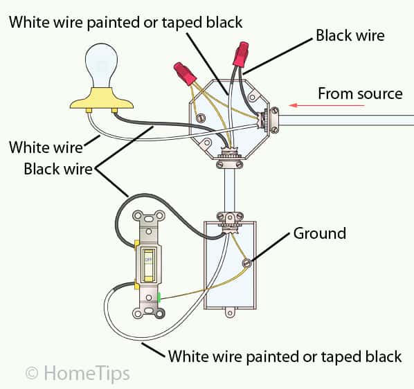
2 Way Switch Single Pole Wiring Diagram

Vt Commodore Ignition Wiring Diagram, Complete Wiring Diagrams For Holden Commodore VT, VX, VY, VZ, VE, VF, 5.36 MB, 03:54, 32,796, John Amahle, 2018-08-01T19:37:41.000000Z, 19, Vt Commodore Ignition Wiring Diagram, to-ja-to-ty-to-my-to-nasz-swiat.blogspot.com, 1272 x 1800, jpeg, bcm pcm 12j swiat nasz, 20, vt-commodore-ignition-wiring-diagram, Anime Arts
A wiring diagram for double pole throw dpdt switch that scientific. Wiring diagram experience devices perfectsocket com. Wiring a 2 way switch. Wiring a 2 way switch.
The “gang” just represents the number of switches on the plate which is also known as “throw”, “rocker” or “dimmer” while the “way” describes the number of controlling circuits per switch e. g. If you are going to install a new one then go for three wire control methods. Pin1 & pin2 of the first. In the schematic diagram, it can be observed that the com terminal in both switches is connected. The l1 edges in two switches will have a connection with the ac supply line whereas the l2 edges in the switches are connected to the light bulb’s one end and the other end of the light bulb is. What is the difference between a 1 pole and 2 pole switch? Both single pole and double pole switches can be thrown at the same time. A pole is the number of separate circuits a switch can control, a single pole switch can operate one circuit, and a double pole switch can operate two or more circuits. Switches are the most common type of switch.
Wiring Two Single Pole Switches : How to Wire and Install Single-pole Switches : Single pole

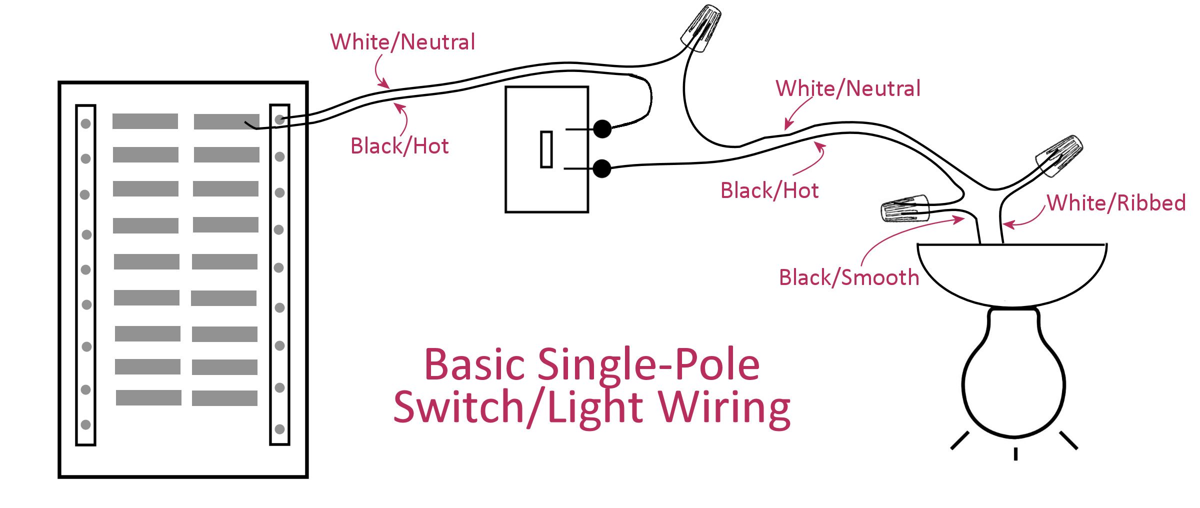
Electrical Basics - Wiring A Basic Single-Pole Light Switch - Addicted 2 Decorating®

Wiring Two Single Pole Switches : How to Wire and Install Single-pole Switches : Single pole

Single Pole, Way Switch Wiring Most 3 Gang 2, Dimmer Switch Wiring Diagram Within Diagrams

Single Pole Switch Diagram 2
Single Pole Switch 2 Wire Nice Elegant 1 Switch 2 Lights Wiring Diagram 58 In Single Pole Dimmer

change out light switch from single switch to double switch | Single Pole Light Switch Wiring

Double Pole Switch Wiring Diagram Light Professional Double Pole Switch Wiring Diagram Awesome

2 Single Pole Switches - 2

Leviton Double Pole Switch Wiring Diagram | Free Wiring Diagram

