120v Solenoid Valve Wiring Diagram

Vt Commodore Ignition Wiring Diagram, Complete Wiring Diagrams For Holden Commodore VT, VX, VY, VZ, VE, VF, 5.36 MB, 03:54, 32,796, John Amahle, 2018-08-01T19:37:41.000000Z, 19, Vt Commodore Ignition Wiring Diagram, to-ja-to-ty-to-my-to-nasz-swiat.blogspot.com, 1272 x 1800, jpeg, bcm pcm 12j swiat nasz, 20, vt-commodore-ignition-wiring-diagram, Anime Arts
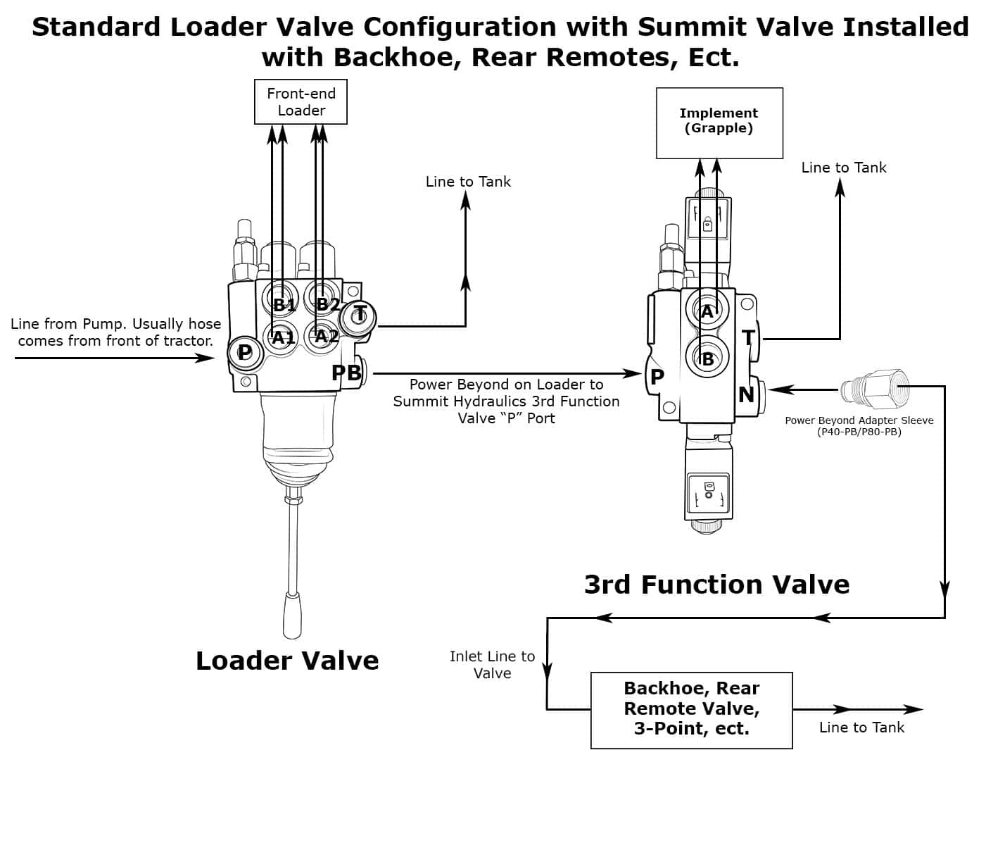
In the above image when the power is off the flow would take place from the compressor p and it would go out through b. How to wire a 2 wire solenoid valve? Solenoid terminal b is the positive battery cable terminal. The starter relay is connected to thenoid terminal m or c.
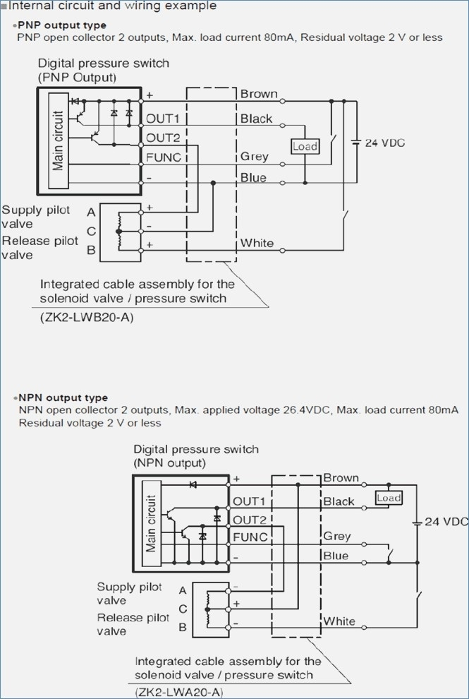
It is connected to the ground terminal of the battery. This is a good place to put a jumper wire if you are using a. Wiring a 3 wire solenoid valve to the w100 controller. [cz_7686] solenoid valve wire diagram wiring diagram inst. omit. kesian. illuminateatx. org. 12v relay wiring diagram switching 120v with wiringmanualpdf. blogspot. com [rm_1661] arduino solenoid valve driver circuit schematic wiring. [rm_1661] arduino solenoid valve driver circuit schematic wiring. I'm looking to control a 110vac solenoid valve with a foot switch. Solenoid valve has 2 wires (normally closed) treadlite foot switch can someone draw up a wiring diagram from 110v power cord 120v solenoid valve wiring diagram.
Asco Red Hat Wiring Diagram 120v

38 120v Solenoid Valve Wiring Diagram - Wiring Diagram Online Source
38 120v Solenoid Valve Wiring Diagram - Wiring Diagram Online Source

Wiring Manual PDF: 120 Volt Solenoid Switch Wiring Diagram

38 120v Solenoid Valve Wiring Diagram - Wiring Diagram Online Source
38 120v Solenoid Valve Wiring Diagram - Wiring Diagram Online Source

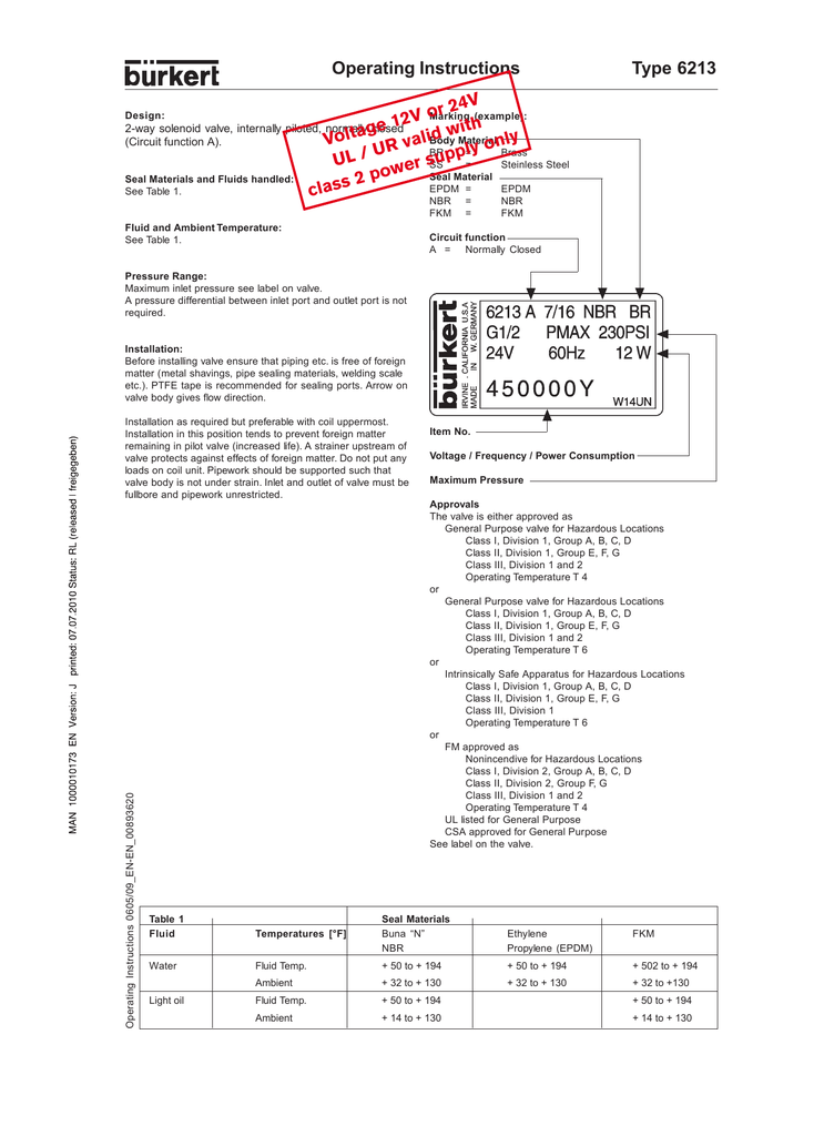
Asco 8263G200-120/60 3/8" 2-Way Solenoid Valve NC 100# Water General Service CV .52
38 120v Solenoid Valve Wiring Diagram - Wiring Diagram Online Source

Wiring Manual PDF: 120 Volt Solenoid Switch Wiring Diagram

42 24vdc Solenoid Valve Wiring Diagram - Wiring Niche Ideas

