12vdc Relay Wiring Diagram

Vt Commodore Ignition Wiring Diagram, Complete Wiring Diagrams For Holden Commodore VT, VX, VY, VZ, VE, VF, 5.36 MB, 03:54, 32,796, John Amahle, 2018-08-01T19:37:41.000000Z, 19, Vt Commodore Ignition Wiring Diagram, to-ja-to-ty-to-my-to-nasz-swiat.blogspot.com, 1272 x 1800, jpeg, bcm pcm 12j swiat nasz, 20, vt-commodore-ignition-wiring-diagram, Anime Arts
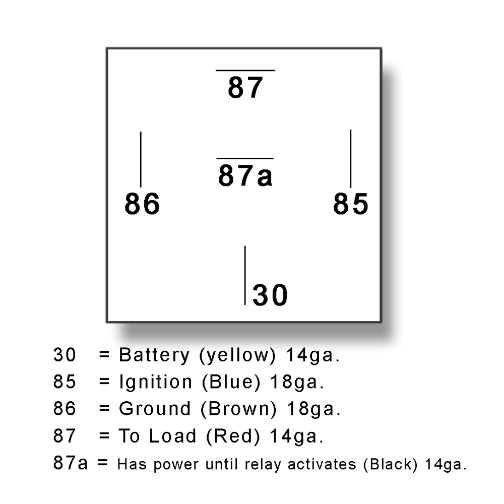
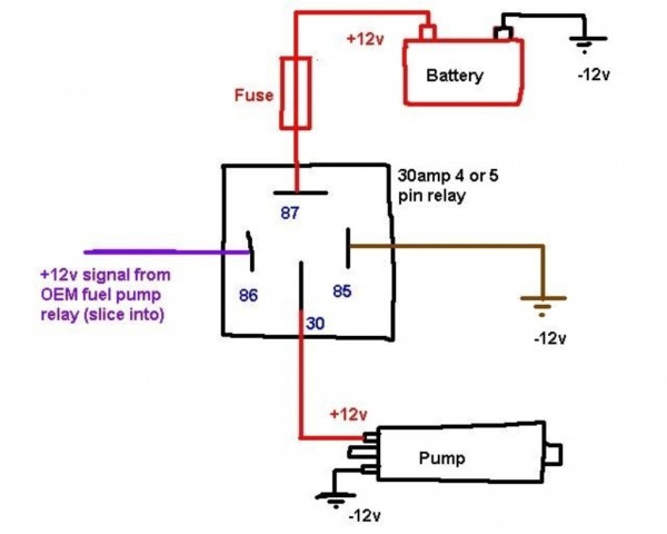
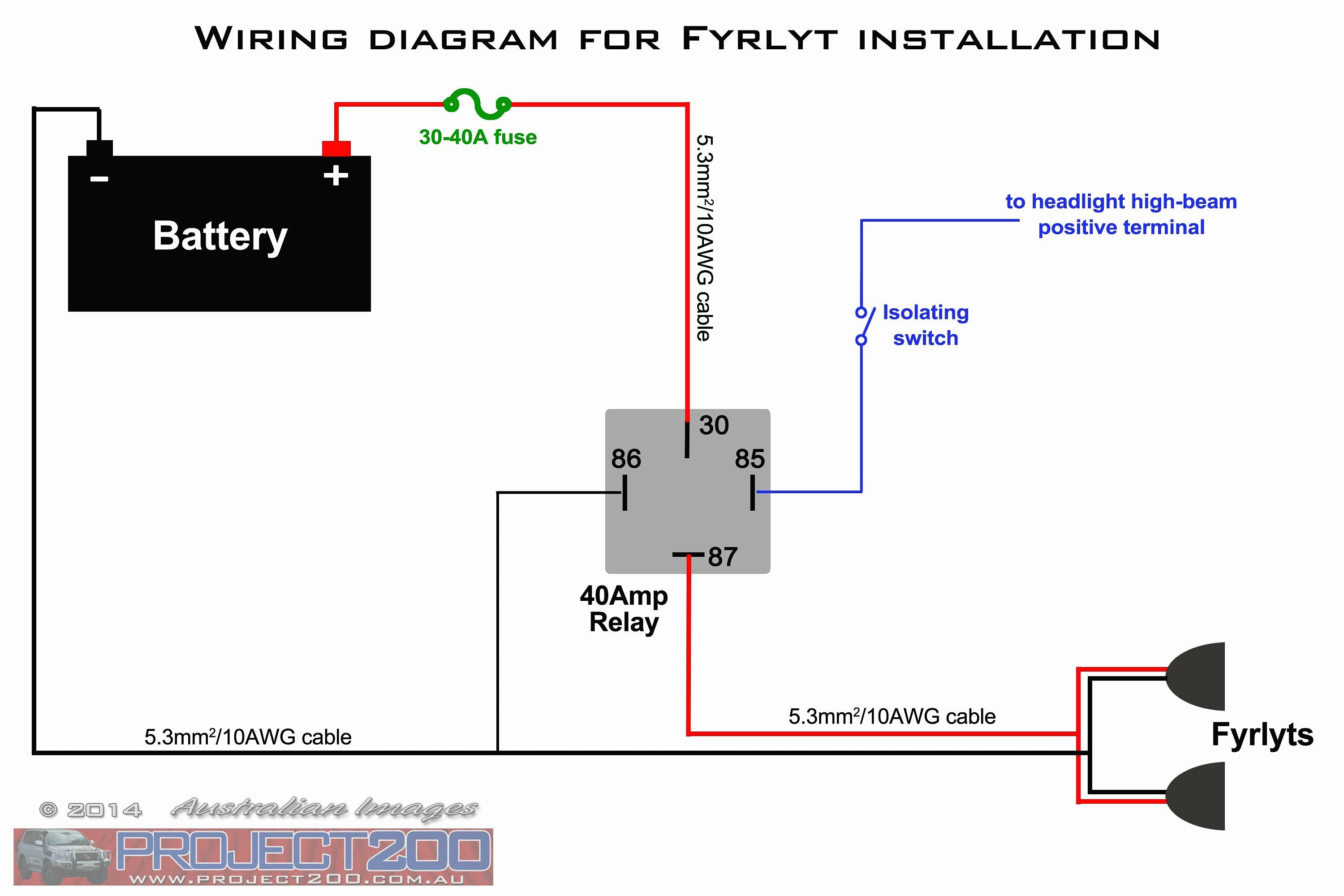
The diagram above is the 5 pin relay wiring diagram. There are different kinds of relays for different purposes. It can be used for various switching. Relay can be the best option to control electrical devices automatically.
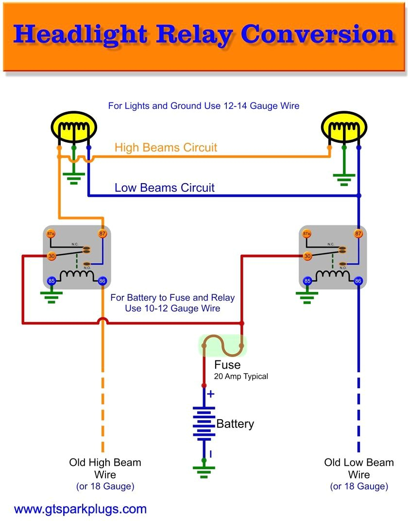
Looking at the diagram, we see the pinout of a typical 12v relay. Note that each pin is numbered. 85 and 86 are the coil pins while 30, 87, and 87a are the contact pins. 87 and 87a are the two contacts to which 30 will connect. If the coil is not activated, 30 will always be connected to 87a. You can think of this as the switch in off. My defender originally came with the original bullbar with spots attached. They use to work when i trigger brights via the steering stalk. The lighting system was poor so i added the headlight relay wiring harness and couple months ago removed bumper and spots.
12vdc Relay Wiring Diagram 4 Pin Relay Wiring Diagram Horn | Electrical diagram, Diagram, Relay

Automotive Relay Guide | 12 Volt Planet
Beautiful 12 Volt Relay Wiring Diagram Symbols #diagrams #digramssample #diagramimages #

Relay Wire Diagram 5ab7826eea718 In 12 Volt Relay Wiring Diagram | Electrical circuit diagram

5 PIN 12V RELAY WITH LED LIGHT INDICATOR - Hagemeister Enterprises Inc. (HEI)

Automotive Relay Circuit Diagram

12 Volt Relay Wiring Diagram | Wiring Diagram

12 Volt Relay Wiring Diagram Sample - Wiring Diagram Sample

Coromal 12 Pin Wiring Diagram - Wiring Diagram

12v Relay Circuit Tags Wiring Diagram Car Amp In 12 Volt Carlplant For Relays 10 in 2020

